Sheet to Sheet Screen Printing Machine
Professional designer and manufacture of CCD machines for ONE STOP SOLUTION.
Language
Professional designer and manufacture of CCD machines for ONE STOP SOLUTION.
The following focuses on the setting of the manipulator. In the manipulator setting here, it involves printing, loading, unloading, alignment and dusting coordinates, loading coordinates
Mechanical keys and operation interface basic key introduction
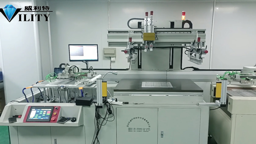
The following focuses on the setting of the manipulator. In the manipulator setting here,it involves printing, loading, unloading, alignment and dusting coordinates, loading coordinates, unloading coordinates and other parameters; so I'll give you a detailed introduction here. First of all, starting from the white square here in the lower right corner, these are the parameters for the loading axis, which is the feeding axis written here, and feeding material to the top of the printing machine table is the feeding axis.
How to set the feeding axis is very simple. The feeding position is also the place where the loading table is. Then when the material is in this place, it is the feeding position, then set up so that the suction cup of the suction robot can just suck the material and keep in one place with it. For example, like this one material, to give you a demonstration. When the original position is like this, it needs to be set as the feeding position, so let the robot move to the left; you can test it, there is a "feeding cylinder" and a "feeding suction cup" on the interface, you can test it to turn on the suction cup of the plastic cylinder. Suction wind open, and then let the feeding suction cup to absorb the material. Look at the robot just parallel to the material, and then the robot above these nozzles, each nozzle is free to move, free to adjust, according to the size of the material, the length of the free to adjust its direction, position and distance. After adjusting the robot here, the value is now 38.56 position coordinates, can be appropriate to go a little ahead. When you get to this position, set it to this position as the coordinates. In the setting screen, click on the blue "Feeding position" and click "Yes", this is the setting of the feeding position.
The second item is the "waiting position", which refers to a waiting time between the printing process, when the material is sucked up, and when the printing and feeding robot movements are completed. Then this position is the waiting position. Waiting position can be appropriately larger than the loading position, for example, the loading position is 33, then the waiting position can be appropriately larger, set to 35, 36, 37, but not too large. This is the waiting position setting.
What is a buffer position? That is, the first piece of material has been fed, the manipulator sends the material to the table, and will continue to catch the second piece of material after returning; When the second piece of material is picked up, but the printing and feeding manipulator behind has not completed the action, the feeding manipulator will pick up the material and send it to the position waiting for feeding, in the middle of which there will be a buffer position. The loading position of the buffer is that after the suction, it will go to the buffer position and wait. After the completion of the previous printing operation, the next one will be carried out. Click open to show you a rough way of setting the buffer position; Setting up the buffer location is simple. The printing press has a net frame, the net frame must be down in the printing process, so when setting the buffer position, we must pay attention to the manipulator can not collide with the net frame, the middle must keep a distance, when setting must pay attention to look at.
CONSULT OUR CUSTOMERS FOR SURPRISE DISCOUNTS
Please provide us with the information below to complete your request. Just leave your email or phone number in the contact form so we can send you a free quote for our wide range of designs!

VILITY is a Professional manufacturer, providing ONE-STOP SOLUTION for intelligent printing industry.