Professional designer and manufacture of CCD machines for ONE STOP SOLUTION.
Language
Professional designer and manufacture of CCD machines for ONE STOP SOLUTION.
FPC is an alternative to chip antennas and is an interesting option for specific embedded designs.
FPC antennas are thin, typically only 0.15 mm, with a peel-off strip and a bonding area that allows them to be secured inside small electronic devices in a variety of configurations. They are supplied with a cable and a connector for fixing them to the bottom covering or housing of the manufacturer's electronics. An FPC is very light, probably less than 0.5g.
FPC is an alternative to chip antennas and is an interesting option for specific embedded designs.
FPC antennas are thin, typically only 0.15 mm, with a peel-off strip and a bonding area that allows them to be secured inside small electronic devices in a variety of configurations. They are supplied with a cable and a connector for fixing them to the bottom covering or housing of the manufacturer's electronics. An FPC is very light, probably less than 0.5g.
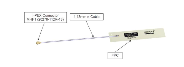
This picture shows the FPC antenna with cable and I-PEX connector.
Advantage: no ground problems
FPC work differently than surface mount device (SMD) chip antennas. The SMD antenna is radiated using the installed ground plane, and its working principle is reciprocation. A dipole antenna uses two radiators, the length of each radiator is related to the wavelength of the frequency used by the antenna. Embedded antennas have a heat sink within their mass, and they use an area on the PCB as their counter plane, often referred to as the ground plane.
For SMD antennas, the length of the ground plane is directly related to the wavelength of the antenna. The correct ground plane length must be provided in the design so that the antenna can operate with good efficiency.
FPC antennas are different in this - they don't need a ground plane to radiate. Therefore, they allow designers more freedom in arranging the components in the circuit in the design.
However, it is important to remember that the coaxial cable becomes part of the antenna. Therefore, when designing the routing of the cable, care should be taken to keep this part of the antenna away from other components that may generate noise and interference.
Place
Because the ground plane is not a design consideration for FPC antennas, the size of the host PCB is not a factor as it is for SMD or chip antennas. However, the placement of FPC antennas still needs to follow some basic rules, as most antennas are sensitive to the environment.
The antenna will radiate in six spatial directions (Figure 2). Ideally, at least three to five of these directions should be clear of obstructions, which will allow the antenna to work efficiently. For other directions with obstructions in the radiation path, there should still be a minimum gap, which will be defined in the antenna manufacturer's datasheet.
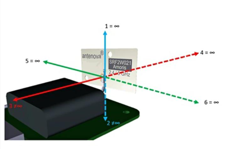
Figure 2,There are no obstacles in the four spatial directions where the antenna is placed
The plastic casing of the device will not act as a barrier unless the material from which the casing is made is glass-filled, or has been painted with metallic paint. Metal objects and components close to the FPC antenna, such as data lines and printed circuit boards (PCB), are often the culprits blocking the signal.
Orientation of FPC
The shape of the device will determine the ideal orientation of the FPC relative to the host PCB. The location of the antenna relative to the PCB will depend on the proximity of the ground (Figure 3).
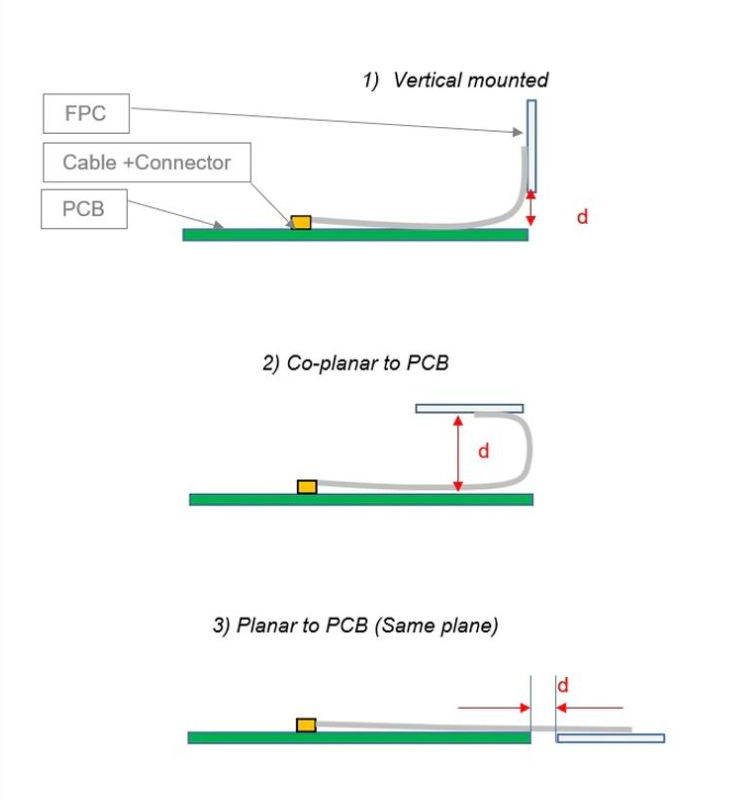
Figure 3. The figure depicts three common configurations of FPC on a host PCB.
Whichever option is chosen, distance (d) becomes a critical dimension in the design. This will be specified in the antenna manufacturer's data sheet.
Device Integration Example
Figure 4 shows an integrated example of an FPC antenna. The main components of the device are in an outer box. The FPC has been adhered to the inside of the plastic housing of the device, and the cables are routed along the PCB so that they do not interfere with any other components. In this case, the FPC is placed on the same plane relative to the PCB. Due to the ultra-thin design of the device, this is the best location for the antenna.
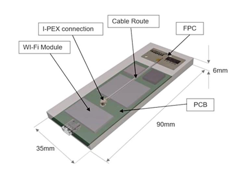
Figure 4. Here, the FPC is integrated into a narrow device
The I-PEX cable for the antenna connects it into the design. The characteristic impedance of all transmission lines within the product is designed to be 50Ω and should be kept as short as possible. All other parts of the RF system, such as transceivers and power amplifiers, should also be designed with 50Ω impedance.
We recommend using a commercial RF design package to create the transmission line layout, taking into account PCB thickness, copper thickness, and dielectric constant. The program will calculate the recommended width of the transmission line, and the appropriate space between the reference ground planes on either side of the antenna feeder to maintain a 50-Ω system impedance.
Are FPC Antennas Right for Your Design?
For small PCBs, SMD antennas may be the most obvious choice, but FPC antennas are widely used in space-hungry applications.
Off-the-shelf FPC antennas are not recommended for the smallest devices, but there are many applications where FPCs work well. They are a particularly useful option for designs where ground plane length and space are constrained.
1: Application Scope
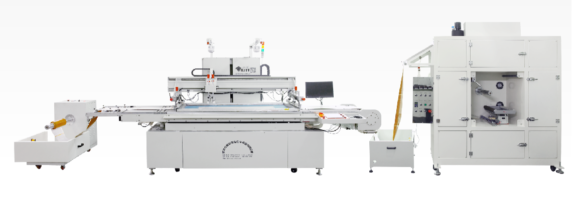
This machine is widely used in FPC,PET, PVC, varies of label,transfer paper (film), floor heating film, geothermal film, electro thermal film, color paper, film, name plate, flexible circuit board, mobile phone keys, Membrane switch, trademark printing, scratch CARDS, self-adhesive stickers, paper, ribbon, aluminum foil and copper foil this roll material silk screen printing.
2: Features and performance
A: Main machine feature---screen printing machine
(1). CCD automatic alignment system, if the similarity is not within the setting range, any abnormal, it will stop and automatically start adjust the alignment successful and continue to work.
(2). Using numerical control motor, printing speed, return to the ink speed can be set in a random block.
(3). Using numerical control motor, printing distance, return to the ink distance can be set in a random data.
(4). Automatic computing printing, and calculate the qty, and printing can be set automatically stop.
(5). photoelectric control feeding and discharging to avoid the surface damage of substrates, can improve the printing quality.
B: The Feeder features:
(1). Photoelectric control feeding, avoid the surface damage of the material.
(2). Feeding speed, time, can adjust at will.
(3). The feeding starting speed, can adjust at will, start frequency starting from 0 up to run slowly, avoid the start too fast, cause the material surface scratches.
(4). Equipped with an automatic protective device.
C: The dryer features:
(1).Circulating hot air drying, temperature adjustable, automatic winding.
(2).The oven cover an small area, 32-60 meters length, which can realize low temperature drying, ensure printed material no shrinkage deformation, multicolor printing.
Name | Parameter | Remark | |
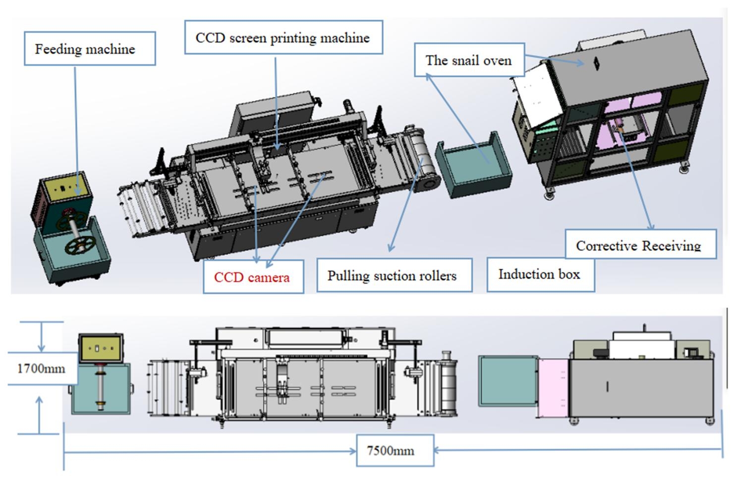
CCD Printing machine | Working place area(mm) | 1000*660 | / |
Max inputting width(mm) | 450 | ||
Max printing area(mm) | 600*450 | ||
Mix printing area(mm) | 400*500 | ||
Max size of screen frame(mm) | 1100*800 | ||
Mix size of screen frame(mm) | 300*200 | ||
printing thickness(mm) | 0.075-0.125 | ||
Mix print skip distance(mm) | 2 | ||
Working voltage (v) | 380-50Hz | ||
Maine machine Max power (kw) | 40 | ||
Working pressure(kg/cm2) | 5-8 | ||
Precision of printing(mm) | ±0.05 | ||
First printing speed | 1000-1200 times / hour | ||
Second printing speed | 800-1000 times/ hour | ||
Scraper stroke(mm) | 900 | ||
CCD precision | ±0.02 | ||
CCD center space | 330mm | ||
Main machine size (mm) | 3300*1600*2200 | ||
Receiving oven | Oven temperature(℃) | 0-190 |
Laminating device can be add in Oven |
Oven working voltage(V) | 380 | ||
Oven max power (KW) | 24 | ||
Max size(mm) | 450 | ||
Oven size (mm) | L2400*W1200*H2100 | ||
Feeding goods max size(mm) | 450 | ||
Feeding machine | Feeder peak voltage(V) | 220 | According to your requirement |
POWER(KW) | 0.3 | ||
Size (mm) | 800*1000*1100 | ||
Raw material →Automatic feeding machine →Automatic printing→Automatic UV or oven →Automatic receiving →End product.
◪ We have a rich experience, technical good, service awareness ahead of the professional team, can be timely and effective solve the problem for you.
◪ Installation and debug machine for you without any charge. Also, giving a technical training for your employees.
◪ All of our machines can have one year guarantee and lifelong maintenance.
CONSULT OUR CUSTOMERS FOR SURPRISE DISCOUNTS
Please provide us with the information below to complete your request. Just leave your email or phone number in the contact form so we can send you a free quote for our wide range of designs!

VILITY is a Professional manufacturer, providing ONE-STOP SOLUTION for intelligent printing industry.